Последние темы
» Вити больше нет!автор bug19 Пн Фев 20 2023, 19:54
» Собираем оригинальный Орион 128
автор bug19 Пн Фев 20 2023, 19:47
» Проблема плющеного экрана ОРИОНА
автор kanzler Пн Ноя 28 2022, 12:05
» Орион 128 и его клоны возрождение 2019-2022 год
автор kanzler Пн Ноя 28 2022, 12:03
» Электроника КР-04. Информация, документы, фото.
автор kanzler Пн Ноя 28 2022, 12:02
» Новости форума
автор kanzler Пн Ноя 28 2022, 11:52
» Орион-128 НГМД запуск 2021 года
автор matrixplus Сб Сен 10 2022, 17:36
» ПЗУ F800 для РК86
автор ведущий_специалист Сб Сен 10 2022, 10:37
» Микропроцессорная лаборатория "Микролаб К580ИК80", УМК-80, УМПК-80 и др.
автор Электротехник Вт Июл 26 2022, 19:33
» Орион-128 SD карта в Орионе
автор matrixplus Чт Июн 02 2022, 09:00
» 7 Мая. День Радио!
автор Viktor2312 Чт Май 12 2022, 10:58
» Серия: Массовая радио библиотека. МРБ
автор Viktor2312 Ср Май 11 2022, 12:17
» Полезные книги
автор Viktor2312 Пн Май 09 2022, 15:07
» Орион 128 Стандарты портов и системной шины Х2
автор matrixplus Вс Май 08 2022, 23:08
» Орион-128 и Орион ПРО еще раз про блоки питания
автор matrixplus Вс Май 08 2022, 19:09
» Орион-128 Программаторы
автор matrixplus Вс Май 08 2022, 19:02
» Орион ПРО история сборки 2021 до 2022
автор matrixplus Вс Май 08 2022, 18:47
» Анонсы монет (New coin).
автор Viktor2312 Сб Май 07 2022, 23:11
» Хочу свой усилок для квартиры собрать не спеша
автор Viktor2312 Сб Май 07 2022, 19:33
» Амфитон 25у-002С
автор Viktor2312 Сб Май 07 2022, 09:38
» Майнер: T-Rex
автор Viktor2312 Вс Май 01 2022, 09:12
» GoWin. Изучение документации. SUG100-2.6E_Gowin Software User Guide. Среда разработки EDA.
автор Viktor2312 Пн Апр 25 2022, 01:01
» GoWin. Изучение документации. UG286-1.9.1E Gowin Clock User Guide.
автор Viktor2312 Сб Апр 23 2022, 18:22
» GoWin. Documentation Database. Device. GW2A.
автор Viktor2312 Ср Апр 20 2022, 14:08
» GOWIN AEC IP
автор Viktor2312 Ср Апр 20 2022, 12:08
Самые активные пользователи за месяц
| Нет пользователей |
Поиск
MINI EPROM PROGRAMMER. (eng)
RUЭВМ :: Электроника :: Программаторы
Страница 1 из 1 • Поделиться

 MINI EPROM PROGRAMMER. (eng)
![]() Viktor2312 Вт Авг 20 2019, 23:29
Viktor2312 Вт Авг 20 2019, 23:29
1
.
____Many constructors have good reasons for preferring a low-cost EPROM programmer with manual data and address to a full-blown programmer operating under computer control. First, they may not have a computer; second, they do not mind spending some time on programming small amounts of data; and third, they object to the expenditure on an instrument that is only occasionally called upon.
____The programmer is definite-Iy not intended for loading huge amounts of data into EPROMs. Even if you eould manage to program bytes faultlessly at a rate of one per second, it would take more than 18 hours to load all 65,536 bytes (64 Kbytes) in a Type 27512 EPROM, the largest the present programmer can handle. Moreovar. it is a common misunderstanding to associate EPROMs with microcomputer systems that require large amounts of data. As has been shown in a number of projects in this magazine over the past few months, there are quite a few occasions whe.re no more than, say, 256 or 512 bytes are involved, such as where EPROMs lunetion as programmable look-up or conversion tables.
____Although the circuit diagram of the mini EPROM programmer (Fig. 1) looks crowded, it should be noted that most components go into the power supply to ensure that the high programming voltage is not applied to the EPROM until the 5 V supply voltage is present ~ the reverse sequence would have disastrous consequences. Also note that an EPROM must never be removed from the working programmer, because the order in which the programming voltage and the supply voltage are removed might just be wrong.
How it works.
____Although the supply cireuit a!ready looks quite crowded in pIaces, it Is not complete without an external regulated power supply to furnish the programming voltage plus about 750 mV. The input volta ge to the eircuit may be edjusted by measuring the programming voltage at point Pv. The programming voltage is determined by the EPROM type and its manufacturer. Regulator IC3 reduces the programming voltage to 5 V which is used to power the EPROM and the programmer circuit. Transistor Tl prevents the programming voltage being applied to the EPROM before the 5 V supply voltage. The transistor is controlled by a monostable multivibrator (MMV), ICh. After this has been trtggered, H5 Q output remains high until it is reset via its LCR input. This input is connected disconnected from the relevant EPROM pin when the programmer is switched off with 5,- The 5 V supply voltage, however, remains present for a short while because the electrolytic capaeitors take some time to discharge. Conversely. ICla can not be set until the +5 V supply voltage is present. The SET input of the MMV is formed by trigger input B, which is connected to network R3-CS.The voltage on Cs takes a few seconds to rise to a Ievel that enables ICla to be set, and, consequently. the programming voltage to be applied to the EPROM. Capaeitor CIOis required only if the CLR input of ICh is erroneously actuated by input voltage Fluctuetions. The value of ClO should be between 100 pF and 10 nF and must be determined empirically. In general, the capacitor must be kept as small as possible. Bi-colour LED D7 indicates the status of the EPROM programm er. The LED turns red (T3off; T, on) if the 5 V supply voltage is present, and green if both the 5 V and the programming voltage are present.
____The circuit around leIb (also a MMV) is a programming pulse generator. When 52 is actuated, a single 50-ms programming pulse is generated. An intelligent programming algorithm with variable prograrnming pulse length is. of course, not feasible in a simple circuit like this. Even if it were availabIe, the total programming time would not be reduced because the data and addresses are set manua11y, which takes much longer than SO ms in any case. The bulk 01 the signals in the programmer circuit emanates from DIP switches and associated pull-up resistors. Addresses are set with 54 and 55, data with 56. Switch 53 is used to seleet the EPROM type. The connections it makes are in accordance with the EPROM data listed in Table 1.
Электрическая принципиальная схема: Скачать
Construction.
____The printed-circuit board for the programmer is shown in Pig. 3. Start the construction by fitting the wire links. Next, fit the resistors and capecitors. Each of the three single-in-Hne (SIL) resistor arrays may be replaced by eight vertically mounted, discrete resistors whose upper terminals are cut short and commoned by a horizontal wire that goes into the hole provided for the +5 V connection of the array.
____The semiconductors are fitted next, with the exception of the LEDs. Je, does not need a heat-sink, and is bolted straight on to the PCB. Mount rotary switch 53,but do not cut its spindie as yet.
____Be sure to mount the components that protrude from the front panel at the correct height above the board. This involves the LEDs, on/off switch 51,programming switch 52, the data/ address DIP switches and the ZIF (zero-insertion force) socket for the EPROM. A good way of achieving the correct height for the DIP switches is to use wire-wrap sockets or simply three or four stacked low-profile IC sockets (see Fig. 2). Much depends on the enclosure used.
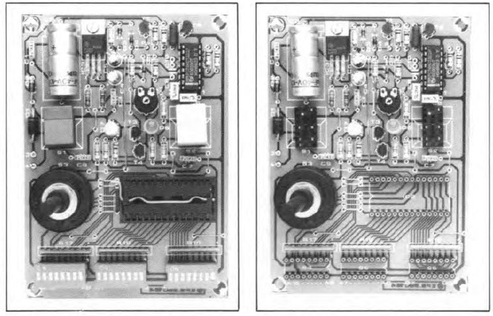
Fig. 2. As shown on these photographs of the assembled peB, IC sockets are perfect for
mounting the push-buttons and the DIP switch blocks. SIL strips are used for the ZIF socket.
The height of the prototype enclosure did not require low-profile IC sockets to be stacked.
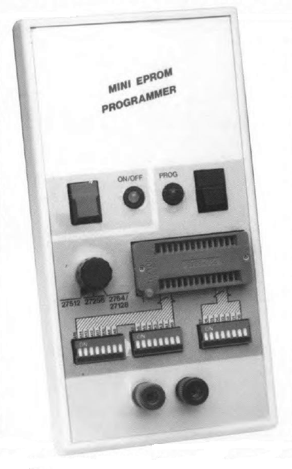
____Figure 4 shows a suggested lay-out for the front panel of the programmer. Make a photocopy of this drawing and use it as a template to cut and drill the metal or ABS front-panel of your enclosure.

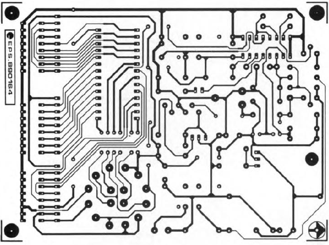
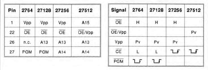
Table 1. EPROM programming data as set by the EPROM type switch on the front panel.
SeHing up.
____Connect the external power supply and adjust it to an output that results in +10.0 V at point Pv (you may have to wait a second or tWQ until Tl is turned on). Adjust PI until the status LED changes colour. This completes the ad justment procedure.
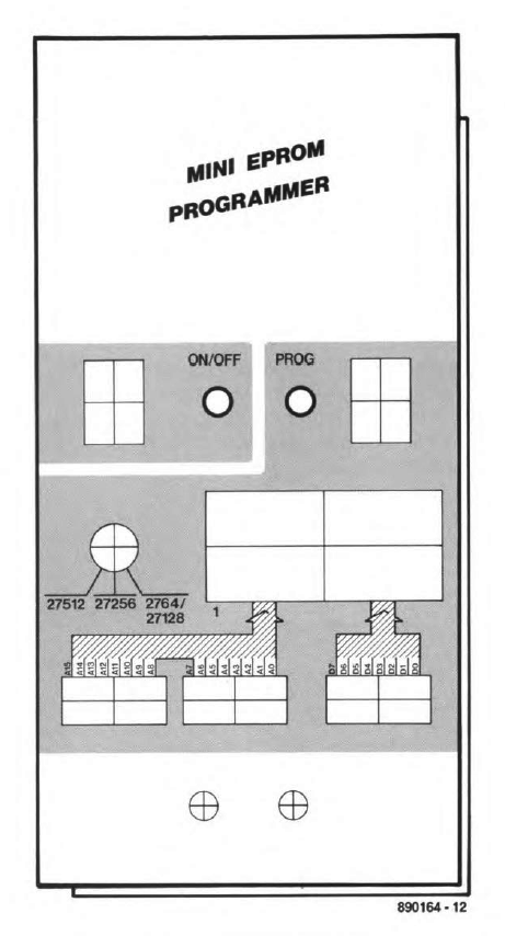
Fig. 4. Suggested front-panel layout shown at true size for easy reproduction.
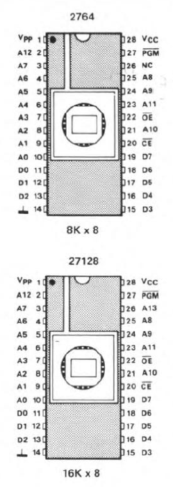

Fig. 5. Pin-outs of the tour members of the 27xxx family that can be programmed.
Do's and don'ts.
____There are a few basic rules to keep in mind when using the mini EPROM programmer:
Картинки в архиве: Скачать
.
MINI EPROM PROGRAMMER.
J. Ruffell
____Many constructors have good reasons for preferring a low-cost EPROM programmer with manual data and address to a full-blown programmer operating under computer control. First, they may not have a computer; second, they do not mind spending some time on programming small amounts of data; and third, they object to the expenditure on an instrument that is only occasionally called upon.
____The programmer is definite-Iy not intended for loading huge amounts of data into EPROMs. Even if you eould manage to program bytes faultlessly at a rate of one per second, it would take more than 18 hours to load all 65,536 bytes (64 Kbytes) in a Type 27512 EPROM, the largest the present programmer can handle. Moreovar. it is a common misunderstanding to associate EPROMs with microcomputer systems that require large amounts of data. As has been shown in a number of projects in this magazine over the past few months, there are quite a few occasions whe.re no more than, say, 256 or 512 bytes are involved, such as where EPROMs lunetion as programmable look-up or conversion tables.

____Although the circuit diagram of the mini EPROM programmer (Fig. 1) looks crowded, it should be noted that most components go into the power supply to ensure that the high programming voltage is not applied to the EPROM until the 5 V supply voltage is present ~ the reverse sequence would have disastrous consequences. Also note that an EPROM must never be removed from the working programmer, because the order in which the programming voltage and the supply voltage are removed might just be wrong.
How it works.
____Although the supply cireuit a!ready looks quite crowded in pIaces, it Is not complete without an external regulated power supply to furnish the programming voltage plus about 750 mV. The input volta ge to the eircuit may be edjusted by measuring the programming voltage at point Pv. The programming voltage is determined by the EPROM type and its manufacturer. Regulator IC3 reduces the programming voltage to 5 V which is used to power the EPROM and the programmer circuit. Transistor Tl prevents the programming voltage being applied to the EPROM before the 5 V supply voltage. The transistor is controlled by a monostable multivibrator (MMV), ICh. After this has been trtggered, H5 Q output remains high until it is reset via its LCR input. This input is connected disconnected from the relevant EPROM pin when the programmer is switched off with 5,- The 5 V supply voltage, however, remains present for a short while because the electrolytic capaeitors take some time to discharge. Conversely. ICla can not be set until the +5 V supply voltage is present. The SET input of the MMV is formed by trigger input B, which is connected to network R3-CS.The voltage on Cs takes a few seconds to rise to a Ievel that enables ICla to be set, and, consequently. the programming voltage to be applied to the EPROM. Capaeitor CIOis required only if the CLR input of ICh is erroneously actuated by input voltage Fluctuetions. The value of ClO should be between 100 pF and 10 nF and must be determined empirically. In general, the capacitor must be kept as small as possible. Bi-colour LED D7 indicates the status of the EPROM programm er. The LED turns red (T3off; T, on) if the 5 V supply voltage is present, and green if both the 5 V and the programming voltage are present.
____The circuit around leIb (also a MMV) is a programming pulse generator. When 52 is actuated, a single 50-ms programming pulse is generated. An intelligent programming algorithm with variable prograrnming pulse length is. of course, not feasible in a simple circuit like this. Even if it were availabIe, the total programming time would not be reduced because the data and addresses are set manua11y, which takes much longer than SO ms in any case. The bulk 01 the signals in the programmer circuit emanates from DIP switches and associated pull-up resistors. Addresses are set with 54 and 55, data with 56. Switch 53 is used to seleet the EPROM type. The connections it makes are in accordance with the EPROM data listed in Table 1.
Электрическая принципиальная схема: Скачать
Construction.
____The printed-circuit board for the programmer is shown in Pig. 3. Start the construction by fitting the wire links. Next, fit the resistors and capecitors. Each of the three single-in-Hne (SIL) resistor arrays may be replaced by eight vertically mounted, discrete resistors whose upper terminals are cut short and commoned by a horizontal wire that goes into the hole provided for the +5 V connection of the array.
____The semiconductors are fitted next, with the exception of the LEDs. Je, does not need a heat-sink, and is bolted straight on to the PCB. Mount rotary switch 53,but do not cut its spindie as yet.
____Be sure to mount the components that protrude from the front panel at the correct height above the board. This involves the LEDs, on/off switch 51,programming switch 52, the data/ address DIP switches and the ZIF (zero-insertion force) socket for the EPROM. A good way of achieving the correct height for the DIP switches is to use wire-wrap sockets or simply three or four stacked low-profile IC sockets (see Fig. 2). Much depends on the enclosure used.

Fig. 2. As shown on these photographs of the assembled peB, IC sockets are perfect for
mounting the push-buttons and the DIP switch blocks. SIL strips are used for the ZIF socket.
The height of the prototype enclosure did not require low-profile IC sockets to be stacked.
____Figure 4 shows a suggested lay-out for the front panel of the programmer. Make a photocopy of this drawing and use it as a template to cut and drill the metal or ABS front-panel of your enclosure.


Table 1. EPROM programming data as set by the EPROM type switch on the front panel.
SeHing up.
____Connect the external power supply and adjust it to an output that results in +10.0 V at point Pv (you may have to wait a second or tWQ until Tl is turned on). Adjust PI until the status LED changes colour. This completes the ad justment procedure.

Fig. 4. Suggested front-panel layout shown at true size for easy reproduction.


Fig. 5. Pin-outs of the tour members of the 27xxx family that can be programmed.
Do's and don'ts.
____There are a few basic rules to keep in mind when using the mini EPROM programmer:
- Before inserting an EPROM, always check the programrning volta ge at point Pv and adjust YOUT power supply to set the eorrect value for the device to be programmed. Next, set the EPROM type on Sa.
- Never insert or remove an EPROM with the programmer switched on.
- And, Hnally, think before actuating the programrning switch!
Картинки в архиве: Скачать
.
Viktor2312- RIP
- Сообщения : 15492
Дата регистрации : 2012-08-10
Возраст : 45
Откуда : Пятигорск


 Похожие темы
» Тех. документация, описания, схемы, разное. Intel
» Техническая документация, описания, схемы, разное. Ч 2.
» Техническая документация, схемы, разное...
» GoWin. Documentation Database. Software. GOWIN Programmer.
» Щупаем Arduino Pro.mini.328P
» Техническая документация, описания, схемы, разное. Ч 2.
» Техническая документация, схемы, разное...
» GoWin. Documentation Database. Software. GOWIN Programmer.
» Щупаем Arduino Pro.mini.328P
RUЭВМ :: Электроника :: Программаторы
Страница 1 из 1
Права доступа к этому форуму:
Вы не можете отвечать на сообщения